Rolling Friction
Jayadeep U.B.
Dept. of Mechanical Engg., IISc.
Introduction
Probably the best thing to begin an article on rolling friction is the invention of wheel, which is arguably the most important invention in the history of mankind[1]. The much better efficiency of wheel compared to sliding in case of locomotion is the best illustration for the difference between sliding friction and rolling friction. For those who are interested in the mechanics of biological systems, wheel is a very interesting device for locomotion, due to its near-absence in the natural world. The only example of a true wheel in living beings is the flagella in some bacteria (Vogel 2000). Of course, the rolling motion itself is much more common, and most of the locomotion mechanisms, if analyzed carefully, would be seen to contain a rolling component. This is due to the high cost associated with sliding, not only in terms of energy, but also due to wear. The reason for rarity of wheel in biological world was thought to be that the evolution never happened to invent wheel, especially because a partly developed wheel is of no use. Evolution requires that each intermediate step to be more beneficial than the previous ones[2]. However, later on a more important reason was pointed out: a wheel is an efficient mechanism for locomotion on hard plane surfaces, which are not so commonly available in the natural world. This tells us one of the fundamental differences between sliding friction and rolling friction: the rolling friction is much more strongly connected to deformations than sliding friction.
When we compare rolling friction and sliding friction, the first thing we notice is that the energy loss in rolling is much lesser compared to sliding (about 2-3 orders of magnitude lesser), provided the bodies considered are reasonably rigid. The advantage of rolling is completely lost in case of soft or highly deformable bodies, as anyone who has tried to ride a bicycle on loose sand is sure to know! Better still; try pushing a motorcycle with deflated tyre. Rolling friction is used to account for a number of energy-dissipating mechanisms in action during rolling. Hence, a better terminology to use would have been “resistance to rolling”, as used by initial researchers like Coulomb. However, if we clearly understand the meaning, the terminology used is not much relevant, and such “historical accidents” can not be corrected easily! The rolling friction could be highly counter-intuitive: the sliding friction has almost no influence on rolling friction, which means that lubrication is ineffective, or can even be counter-productive. However, we will see that the first mechanism proposed for rolling friction, suggested by Reynolds, is based on sliding friction. Further, we will see that if we introduce a “rolling frictional force” at the point of contact, the mechanics can go wrong completely.
Though the magnitude of energy loss in rolling friction is comparatively smaller, it is extremely important in the technological scenario due to the sheer number of applications involving rolling. For example, one of the major causes of energy loss in automobiles is the rolling friction between the rubber tyres and the road, thus explaining the higher efficiency of rail locomotives, where steel rollers roll on the steels tracks resulting in reduced rolling friction. Also, the lack of understanding about rolling friction can lead to inefficient designs, especially since the remedial steps like lubrication does not help in reducing rolling friction, in general.
In this article, we will discuss the difference between sliding friction and rolling friction from a purely mechanics perspective, and the fundamental mechanisms of rolling friction in the real world, which obviously are much more complicated. Few case studies will be considered to clarify the difference between the sliding friction and rolling friction, using hypothetical continuum for both the roller and the surface, in the next section. In the third section, various hypotheses about the mechanisms of rolling friction will be discussed in a chronological order, considering only the major contributions. Finally the conclusions will be given, wherein the mechanisms will be arranged based on their relative significance, which obviously can not be perfectly correct!
Mechanics of Rolling Friction
As mentioned earlier, we shall discuss the mechanics of rolling friction and sliding friction using a few case studies, with the aim of clarifying the difference between the two. We shall consider the configuration in which a rigid cylindrical roller rolls on a plane surface, with both the roller and surface to be assumed of hypothetical continuum, completely disregarding the atomic nature of the real materials. We will start with the simplest case of free rolling and progressively move on to more complicated cases. It will be shown that deformations are a must for occurrence of rolling friction from this point of view.
Case Study I – Free Rolling or Inertial
Rolling:
We consider the case of rigid cylinder rolling without slipping on a rigid horizontal surface, as shown in figure 1. This case is usually called free rolling or as inertial rolling by Russian school of mechanicians. It can be seen from the free body diagram, that the weight (or vertical force on the roller) will be exactly balanced by the normal reaction from the surface, since there can not be any acceleration perpendicular to the surface. The only possible tangential force is the frictional force at the point of contact (strictly speaking, the line of contact perpendicular to the plane of paper). If there is a frictional force towards left, it would reduce the center-line velocity, as expected, but will have a net torque on the wheel, which should increase the angular velocity. However, the kinematics of pure rolling requires that the angular velocity and velocity be directly related through the radius of the wheel (r×ω = v), and hence can not change independently. Hence, there can not be a frictional force towards left. On similar lines, it can be shown that a frictional force towards right also cannot be present. This implies that there is no frictional force acting in this case of free rolling, and the velocity of the roller remains constant. Obviously, there is no rolling friction as well.
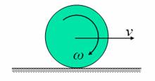
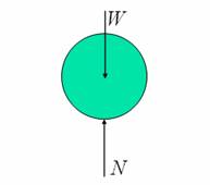
Figure 1: Free rolling,
and corresponding free body diagram of the roller
Case Study II-A – Accelerated rolling down an incline:
This case also has similar configuration to the case above, except that the surface is not horizontal, but makes an angle with the horizontal, as shown in figure 2. Figure 2 also gives the free body diagram, and the equations of motion.
Figure 2: Accelerated
rolling down an incline, corresponding free body diagram of the roller and
the equations of motion
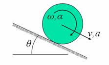
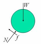
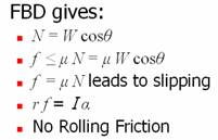
From free body diagram, we can get the sliding frictional force that is acting, as shown in figure 2. If the required frictional force as obtained from this calculation is greater than the maximum frictional force that can be developed (coefficient of static friction times the normal force), pure rolling is not possible; there will be sliding along with rolling. In this case also, there is no rolling friction (since there is no loss of energy – sum of kinetic energy and potential energy remains constant).
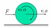
Case Study II-B – Accelerated Motion on a
Horizontal Surface:
We consider the same configuration as discussed in Case Study I. It is evident that there should be an external force (or torque) acting on the cylinder so as to accelerate it. Hence, we shall consider the case of a cylinder with external tangential force acting on it as shown figure 3. This case is similar to that of a driven wheel in an automobile. The free body diagram of the roller, and the equations of motion are also given in the figure.
Figure 3: Accelerated
rolling on a horizontal surface, corresponding free body diagram of the
roller and the equations of motion.
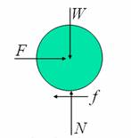
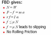
As seen from the free body diagram, in this case also there is sliding friction, but there is no rolling friction (since the net energy – sum of kinetic energy and work done by the force – remains constant).
It is of interest to consider two related cases:
- Applied tangential force in the opposite direction: It is obvious that the velocity should reduce in this case. Drawing the free body diagram can convince us that the frictional force will be in the opposite direction. Equations of motion also can easily be modified to account for this change.
- Torque is applied on the wheel: Let us consider the case of an accelerating wheel, and the decelerating one can easily be obtained from it. This case is similar to that of a driving wheel in an automobile. When there is acceleration, and the only tangential force that is acting is the frictional force, it has to be towards the right, which is obvious if the tendency for relative motion between the wheel and surface is studied. It is interesting to note that the direction of sliding friction, in the case of an accelerating wheel itself, depends on whether there is force acting on it or torque, i.e., during acceleration or deceleration, the direction of frictional force on the driving and driven wheels of an automobile are opposite to each other! This should convince us the advantage of having four-wheel drive vehicles in difficult terrains.
Case study III – Rolling with Deformation:
All the case studies we considered so far did not have rolling friction. In order to have rolling friction, there should be deformation during rolling. For the convenience of analysis, let us consider the case of a rigid cylinder rolling on a deformable surface as shown in figure 4. Note that the deformations shown in the figure are greatly exaggerated for clarity.
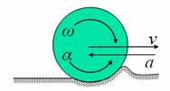
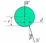
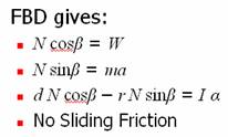
Figure 4: Rolling with
deformation on a horizontal surface, corresponding free body diagram of the
roller and the equations of motion.
As seen from the free body diagram, the point of action of the normal reaction force is shifted to the right, and is at an angle with the vertical direction. This results in a vertical component and a horizontal component for the normal force. The horizontal component can be related to the deceleration of the cylinder, as shown in figure 4. The net moment of the normal reaction force about the centre will be so as to satisfy the kinematical relation between angular acceleration and linear acceleration. It is also seen that the sliding frictional force is negligible. The reason, why we cannot introduce a “rolling frictional force”, and proceed with the analysis, should be evident now. This also means that introducing a terminology like “coefficient of rolling friction” could be misleading, unless the implications are clearly understood.
From these case studies we can conclude that from a pure continuum mechanics perspective, deformation is a must for the rolling friction to occur. Further, the sliding friction and the rolling friction are not directly related. Hence, it could even be misguiding to use the name “rolling friction”; however, it has become so commonly used that it might not get reverted to “resistance to rolling” in future. In the next section, we shall consider the various mechanisms, which manifest themselves as rolling friction. It will be seen that the real life is much more complicated than the continuum mechanics point of view, we adopted in this section.
Physical Mechanisms of Rolling Friction
Even though it was not about the mechanisms of rolling friction, probably the first significant step towards the understanding of rolling friction was by Coulomb in 1781. Based on the experimental studies, he proposed the two famous laws of rolling friction, i.e., provided the materials are the same:
- Resistance to rolling is directly proportional to the load and
- Resistance to rolling is inversely proportional to the diameter of the roller.
The later studies showed that these laws are only approximately true; however, they are commonly used as first approximation.
Reynolds (1876): The first serious study towards the physical mechanism of rolling friction was by Reynolds, whereby he proposed that the rolling friction is due to the slip taking place within the contact area, since real objects can never contact at a point or a line. To indicate this connection, he used the name “rolling friction”, instead of “resistance to rolling” as used by Coulomb, which appears to have remained in literature, though the later studies shown that the interfacial slip is only a minor component of rolling resistance. This theory was able to satisfactorily explain the higher value of rolling friction in deformable surfaces, as it will lead to larger interfacial slip. Heathcote (1921) proposed a more significant mechanism of slip in case of spherical rollers, rolling on a soft surface. He showed that the surface speed of different points of a rolling sphere is different; however must travel the same distance on the surface, which necessitates macro-slip to occur as compared to the micro-slip suggested by Reynolds.
The major difficulty with this theory was the observation that lubrication has negligible effect on rolling friction; it is even found to increase rolling friction in some cases. Reynolds was aware of this issue; he tried to explain it by arguing that the reduction in coefficient of friction due to lubrication could lead to increased slip, and an increase in the area undergoing slip. These effects oppose that due to reduced coefficient of friction, and hence lead to the negligible effect of lubrication on rolling friction as seen in the experiments. However, this explanation appears to be unsatisfactory, and the later studies showed the interfacial slip to be an insignificant mechanism.
Tomlinson (1929): Tomlinson proposed the Molecular Theory of Friction, which suggests that the sliding as well as the rolling friction is due to the hysterisis in adhesion between the atoms of the roller and the surface. He conducted experiments, which proved that the Reynolds type micro-slip is totally insufficient to explain the observed values of rolling friction. Further, if significant, such a micro-slip would have lead to fretting in his experiments, which was not observed. Hence, he suggested that when a roller rolls over a surface, the atoms are pulled from their equilibrium position, which on reaching a critical distance flick back to their original position. The hysteresis (molecular adhesion hysteresis) in this process leads to energy dissipation, resulting in rolling friction.
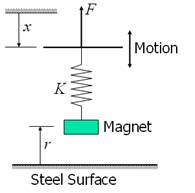
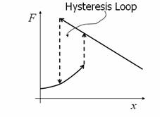
Figure 5 gives a macroscopic illustration of adhesion hysteresis. Consider a magnet suspended through a spring, near a (ferromagnetic) steel surface. Gravity, being a constant force and much weaker, can be ignored. Since, there is always, a magnetic force, varying as the inverse square of the separation (r), a force F needs to be applied even for small values of x (large r). This force F will always be equal to Kδ. When suspended, force on the magnet due to spring will be same as this value, as can be seen from equilibrium equations of the magnet. On gradually increasing x (bringing the magnet closer to the surface), the magnetic force increases as shown by the lower curve. From our physical experience, we know that such continuous increase can not take place till the magnet reaches the surface; the magnet will jump-to-contact with the surface, from a finite distance. This happens when the rate of increase of magnetic force with the separation becomes higher than the stiffness of the spring, as shown in figure. Now if we tried to pull away the magnet, which is already in contact, we need to apply a larger force (since r is much smaller), which is shown by the straight line above (since spring stiffness is assumed to be a constant), or in other words, x has to be smaller than that corresponding to jump-to-contact. Hence, we have a hysteresis loop as shown in the figure. Since the energy received back is the area below the lower curve, while the energy spent is the area below the upper curve (straight line), there is net loss in energy during this hysteresis loop, given by the area of the loop. The molecular adhesion also works in similar manner, except that the process is completely nonlinear, and there will be a number of such loops taking place at the same time.
Figure 5: Illustration of
adhesion hysteresis at macro-scale.
The difficulty with this theory also
is that it is incapable of explaining the negligible effect of lubrication,
even though the adhesion is critically influenced (reduced) by the presence of
a lubricant film. However, later on
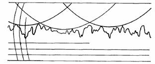
Bikerman (1949): Bikerman conducted a series of experiments by rolling stainless steel balls on a brass plate. The brass plate had surface roughness heights in the size range 0.02 – 3 microns, while the surface of the balls (of radii 1.59 – 6.35 mm) was much smoother. It was observed that the rolling friction was higher for rougher surfaces. The experiments were conducted in such a manner that the other effects like adhesion, elastic deformation and capillary forces were negligible. It was hypothesized that the balls can rest on hills, while the tilting experiments were carried out, thus resulting in higher rolling resistance for rough surfaces (see figure 6). Good quantitative agreement was obtained in case of roughest surfaces considered, while it was poor for smooth surfaces. Therefore, it can be concluded that the surface roughness can have a significant effect on rolling friction, only if it has a significant magnitude (height of hills) in comparison with the radius of the roller (of the order of 0.1% of the roller radius).
Figure 6: Illustrating
how the surface roughness can increase rolling friction (Bikerman 1949).
Eldredge and Tabor (1955), Tabor (1955): In a sequence of two papers in 1955, Tabor and Eldredge discussed probably the most important mechanisms (from a practical engineering perspective) of rolling friction. The first one by Eldredge and Tabor was on the effect of plastic deformations, and the second by Tabor discussed the effect of elastic hysteresis. They did experiments by rolling hard steel spheres on softer metallic, and rubber surfaces. Repeated traversals on same tracks were carried out to study the effect on rolling friction.
In case of steel on metal, especially during the initial traversals, the main cause of rolling friction was the energy dissipation due to plastic deformations. It is obvious that the plastic deformation will reduce with each traversal, and the rolling friction also was found to reduce with each repeated traversal on the same track, thus giving a good correlation. After a large number of traversals, the predominant reason for rolling friction becomes the elastic hysteresis, since no further plastic deformations take place. Work hardening will advance this change of mechanism from plastic deformation to elastic hysteresis. This theory was successful in explaining the negligible effect of lubrication, as the plastic deformation or elastic hysteresis will not be influenced significantly by the presence of a lubricant film.
In case of steel on rubber, the predominant mechanism is the elastic hysteresis, as the permanent deformations will be nearly absent. Figure 7 shows a typical elastic hysteresis curve exhibited by viscoelastic materials like rubber. Since the energy input during loading is higher, by the magnitude of area of the hysteresis loop, than the energy obtained back during unloading, net energy needs to be spent in each loading-unloading cycle. This appears as the energy loss during rolling friction.
Figure 7: Stress-strain
diagram of a viscoelastic material showing the hysteresis loop

Derjaguin and Smilga (1963): Derjaguin and Smilga showed the effect of electric double layer formed when dielectric/semiconductor cylinders roll on metallic surfaces, or vice versa on rolling friction. They showed that the asymmetry created in the electric double layer about the point of contact due to rolling results in a moment opposing the rolling motion. It was shown that under these conditions, it could be a significant component of rolling friction, especially if the surface conductivity and the gas pressure are low.
Kendall (1975):
Conclusions
The rolling friction is used to account a number of various mechanisms, which account for the loss of energy during rolling, and hence it is actually a resistance to rolling more than a friction. Purely from a mechanics perspective, if the roller and surface are perfectly rigid there can not be any rolling friction or in other words, the rolling friction is closely related to the deformations occurring. Significant differences exist between rolling friction and sliding from a mechanics perspective, as well as based on the physical mechanisms. The physical mechanisms leading to rolling friction, ordered according to their relative significance from a practical engineering perspective, are:
- Plastic deformation
- Elastic hysteresis
- Adhesion hysteresis
- Electric double layer
- Interfacial slip, capillary force etc.
The reasoning, given from a pure mechanics perspective above, is expected to fit in as the second or the third item in this list. As concluding remark, in view of the complexities already seen, Coulomb’s laws will only be satisfied approximately, and should be used as a first approximation only.
References
1. Vogel S., Life’s Devices – the Physical World of Animals and Plants, Universities Press, 2000.
2.
Shames I.H., Engineering
Mechanics – Statics and Dynamics, Fourth Edn., Prentice Hall of India.
3.
Reynolds, O., On Rolling
Friction, Phil Trans 166 (1876), 155-174.
4.
Tomlinson, G., A Molecular
Theory of Friction, Phil. Mag. 7 (1929), 905.
5.
Bikerman, J.J., Effect of
Surface Roughness on Rolling Friction, J. Appl. Phys. 20 (1949)
285-296.
6.
Eldredge K.R., Tabor, D.,
Mechanism of Rolling Friction – I. The
7.
Tabor, D., Mechanism of
Rolling Friction – I. The
8.
9.
Derjaguin B.V. Smilga V. P.,
Electrostatic Component of Rolling Friction Moment, Selected Works-3 (1963) 296-306.
10.