AUGER ELECTRON SPECTROSCOPY
|
INTRODUCTION
· The secondary electron emitted due to the incident electron beam produces a vacancy in the lower energy level (usually K shell)
· This vacancy can be filled by an electron in an outer shell with higher energy
· If the electron with the higher energy fills this vacancy, there are two possibilities
o It can emit X rays (Radioactive process)
o It can emit an electron (Non-radioactive process)
· The latter is known as an Auger electron which is produced by the knocking out of a higher energy level electron by the energy which comes out when the vacant space is filled by an electron with higher energy
· 3 electrons participate in emission of Auger electron
o Emitted secondary electron
o Electron which jumps from higher level to occupy the vacancy
o Electron (Auger) which is emitted due to the energy from jumping of the electron
o Hydrogen and Helium don’t produce Auger electron as they have less than 3 electrons
· The energy of the Auger electron is a fixed amount and hence is lost if the electron is coming from an atom which is away from the surface of the specimen
· Only atoms very close to the surface of the specimen can emit the Auger electron
· The energy of the Auger electron is a characteristic of the element. Hence by determination of the energy of the Auger electron an idea about the composition of the specimen can be obtained
· Consider that the K Shell electron was emitted as a secondary electron and it was occupied by an L shell electron which in turn knocked out another L shell electron as Auger electron. This case would be represented by the notation KLL
· The energy of the Auger electron as detected by the detector can be obtained by the expression
![]()
Where ![]() is the Kinetic energy of the electron as
detected by the detector and
is the Kinetic energy of the electron as
detected by the detector and ![]() is the energy of the electron in the K
shell and
is the energy of the electron in the K
shell and ![]() is the energy of an electron in the L Shell
and
is the energy of an electron in the L Shell
and ![]() is the work function of the detector
is the work function of the detector
HOW IT WORKS?
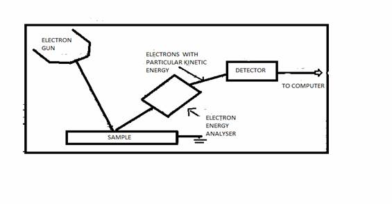
The schematic of the experimental arrangement for basic AES is shown in Fig. below. The sample is irradiated with electrons from an electron gun. The emitted secondary electrons are analyzed for energy by an electron spectrometer. The experiment is carried out in a UHV (Ultra high vacuum) environment because the AES technique is surface sensitive due to the limited mean free path of electrons in the kinetic energy range of 20 to 2500 eV. The essential components of an AES spectrometer are
· UHV environment
· Electron gun
· Electron energy analyzer
· Electron detector
· Data recording, processing, and output system
Electron Energy Analyzer & Electron Detector
The function of an electron energy analyzer is to disperse the secondary emitted electrons from the sample according to their energies. An analyzer may be either magnetic or electrostatic. Because electrons are influenced by stray magnetic fields (including the earth’s magnetic field), it is essential to cancel these fields within the enclosed volume of the analyzer. The stray magnetic field cancellation is accomplished by using Mu metal shielding. Electrostatic analyzers are used in all commercial spectrometers today because of the relative ease of stray magnetic field cancellation.
The dispersed secondary electrons are
received in the electron detector. Detector communicates the energy with
respect to time data to the computer attached with it. The data is analyzed to
find out the Auger peak. An auger analysis is normally based on measurements of
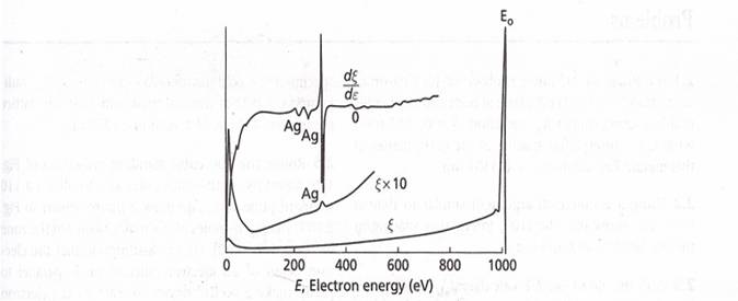
the strengths of Auger peaks in a plot of![]() , the back scattered electron energy per
unit energy interval, versus E, the energy of electrons. This energy flux is
simply equal to the electron energy times the number of electron per unit
energy interval, that is,
, the back scattered electron energy per
unit energy interval, versus E, the energy of electrons. This energy flux is
simply equal to the electron energy times the number of electron per unit
energy interval, that is,![]() . Such a spectrum is depicted for a pure
silver specimen bombarded by 1000 V electrons in the lower curve of figure
shown below. Note that it is very difficult to resolve the Auger peaks on this
curve because they are small and super imposed on a strong background signal
due to backscattered electrons. If
. Such a spectrum is depicted for a pure
silver specimen bombarded by 1000 V electrons in the lower curve of figure
shown below. Note that it is very difficult to resolve the Auger peaks on this
curve because they are small and super imposed on a strong background signal
due to backscattered electrons. If ![]() is multiplied by 10 and the results
replotted, the intermediate curve in the figure is obtained. The Auger peaks
are now more pronounced, but still difficult to resolve. This problem can be
solved by plotting the derivative of
is multiplied by 10 and the results
replotted, the intermediate curve in the figure is obtained. The Auger peaks
are now more pronounced, but still difficult to resolve. This problem can be
solved by plotting the derivative of ![]() with respect of E as in the uppermost
curve of figure. The resulting
with respect of E as in the uppermost
curve of figure. The resulting ![]() curve clearly shows evidence of several
peaks that fall within the range of energies between approximately 240 and 360
eV.
curve clearly shows evidence of several
peaks that fall within the range of energies between approximately 240 and 360
eV.
WHAT IT DOES?
The high surface sensitivity of AES is due to the limited mean free path of electrons in the kinetic energy range 20 to 3000 eV. Auger electrons, which lose energy through plasma losses, core excitations, or interband transitions, are removed from the observed Auger peaks and contribute to the nearly uniform background on which the Auger peaks are superimposed. Because phonon losses are small compared with the natural width of Auger peaks, they do not affect the Auger escape depth. Hence the Auger yield is not dependent on the sample temperature.
Because the Auger transition probability and Auger electron escape depth are independent of the incident electron beam energy, Ep, the dependence of the Auger peak amplitude on Ep is governed completely by the ionization cross-section of the initial core level. Ionization occurs primarily by the incident electrons during their initial passage through the escape depth region (5 to 25Å thick). The backscattered primary electrons can also contribute to the Auger yield when the incident beam energy is substantially greater than the binding energy of the core level involved.
Variables Involved in the Production of Auger Electrons
An inner shell vacancy can be produced through a variety of methods, such as irradiation with electrons and X rays or bombardment with argon ions. Electron impact is usually used for producing Auger lines for analytical purposes. It provides an intense beam that can be brought to a fine focus. X-ray irradiation has its value in providing less radiation damage and better peak-to-background ratios.
High-Energy Satellite Lines
High-energy satellite structures have been observed in the Auger spectra of solids. The presence of such a structure has been interpreted as being due to plasmon gains. It is also believed that the high-energy lines arise from an initial multiple ionization or perhaps resonance absorption. The question of Auger satellites in solids is still under active consideration.
Characteristic Energy Losses
Electrons ejected from a solid can suffer characteristic energy losses, usually due to plasmaon losses. Because Auger spectra are generally rather complex and often not well resolved and are spread over a considerable range of energies, peaks from characteristic energy losses are much more difficult to disentangle from the normal Auger spectrum than is usual in the case of photoelectron spectroscopy.
Also, the surface contamination will alter the nature of the characteristic loss peaks considerably.
Charging in Nonconducting Samples
Charging as a result of an impinging beam of electrons on a nonconductor is a particularly serious problem in Auger spectroscopy. Often the charging and the resulting non uniform surface potential prevent a meaningful Auger spectrum. However, this problem often can be overcome by choosing the proper angle of incidence and the energy of the primary electron beam. The important factor is the ratio δ (the number of secondary electrons leaving the target to the number impinging on the target). If δ = 1, the charge is stabilized. If δ < 1, the charge is negative, and if δ > 1, it is positive. The choice of impact energy is also important. The factor δ becomes less than 1 if the energy of the impinging beam of electrons is either too large or too small. Generally, the primary beam energy lies between 1.5 and 3.0 keV depending on the application and the resolution required.
Scanning Auger Microscopy
With a finely focused electron beam for Auger excitation, AES can be used to perform two-dimensional surface elemental analysis. In this setup, the electron gun operation is similar to that used in conventional scanning electron microscopy (SEM). A set of deflection plates raster the electron beam on the sample. The scanning Auger system can be used to perform point Auger analysis with a spatial resolution on the order of 3 µm by using a minimum beam size of about 3 µm or to obtain a two-dimensional mapping of the concentration of a selected surface element. The low-energy secondary electron or absorbed current displays are used to monitor the surface topography and locate the areas of interest on the sample. To obtain an elemental map, the intensity of the display is controlled by the magnitude of the selected Auger peak. The most negative excursion in the differentiated Auger spectrum is taken as a measure of the Auger current. A two-dimensional elemental map of the surface is obtained by set-ting the pass energy of the electron spectrometer at the negative excursion of the Auger peak of interest. While the output of the lock-in amplifier is used to modulate the intensity of the record display as the electron beam is rastered across the sample. Three-dimensional analysis of the surface of a sample can be obtained by using a combination of scanning Auger microscopy and sputter etching.
Applications:
Auger electron spectroscopy is a very powerful surface analytical technique that has found applications
in many fields of solid-state physics and chemistry.
·
AES is used to monitor the elemental composition
x D x ∑ I i ⁄ Si)
of surfaces during physical property measurements.
· Several phenomena such as adsorption desorption, surface segregation from the bulk, measurement of diffusion coefficients, and catalytic activity of surfaces have been investigated using AES.
· It has also been used to study the surface compositional changes in alloys during ion sputtering. Chemical properties such as corrosion, stress corrosion, oxidation and catalytic activity and mechanical properties such as fatigue, wear, adhesion, resistance to deformation processes, and surface cracking depend on surface properties.
· Similarly, grain boundary chemistry Influences mechanical properties such as low- and high-temperature ductility and fatigue, chemical properties such as inter-granular corrosion and stress corrosion, and electrical properties.
· AES has been used to relate surface and grain boundary chemistry to properties of materials. AES has proved to be extremely valuable compared to most other techniques, which are limited by either large sampling depth or poor sensitivity.